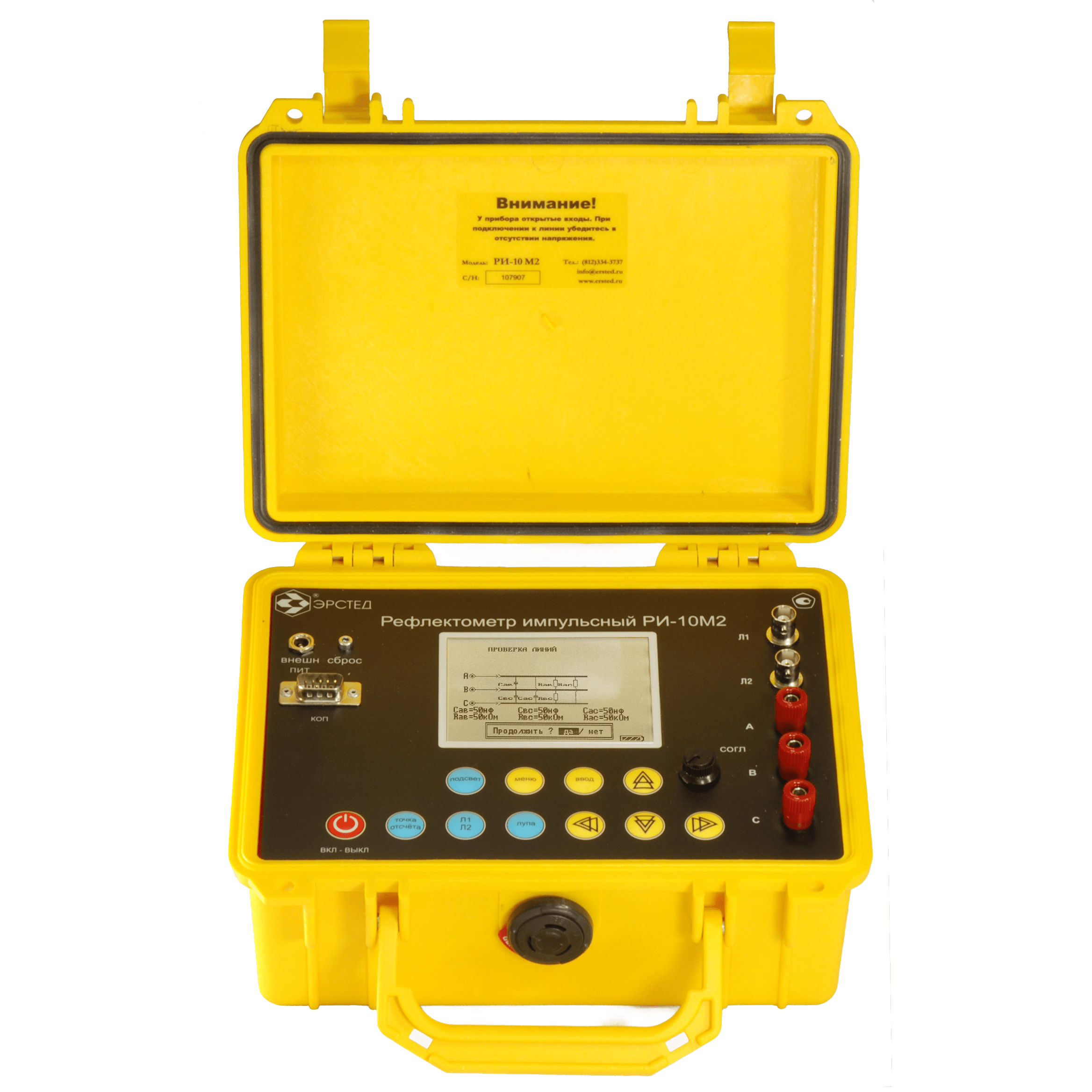
Cable Fault Locator TDR RI-10M2 "SWIFT"
with Bridge module
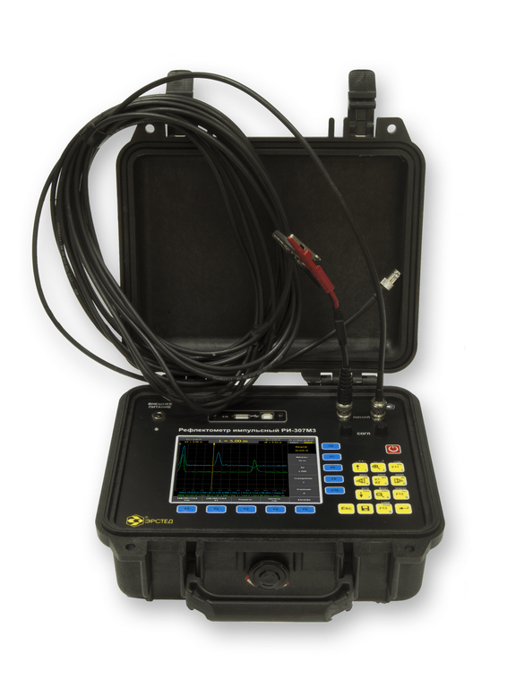
Cable Fault Locator
TDR RI-307М3 "SWIFT" High-precision 2-channels
The search for faults in the SODK makes special increased demands on the measuring capabilities of the reflectometer. Universal locators SODK, intended for measurements on communication and power engineering cables, generally do not fully meet these requirements either in terms of accuracy class or in terms of service functions. What are these requirements?
The devices for the UEC system must provide sufficient bandwidth. The heating main, unlike the cable route, is initially heterogeneous, since the pipes have different wave impedances and reflections from the joints are difficult to avoid even with ideal installation. Each joint is visible on the reflectogram as a burst, the degree of “blur” of which depends both on the frequency characteristics of the trace and on the quality of the receiving path of the device. Blurry responses from seams greatly complicate the interpretation of traces, since the seams are physically close, and their “blurry” responses can overlap both on each other and on responses from damage. The blurring of the reflected signal is associated with the bandwidth of each of the components of the “Device – Connection cables – Heating main” system. Thus, to ensure the best measurement quality and a high degree of trace detail, it is necessary to:
- use devices with sufficient bandwidth;
- exclude cables from the system that differ sharply from the parameters of the UEC system in terms of wave impedance and linear attenuation (for example, NYM cable);
- ensure high-quality installation of joints and, if possible, control the wave resistance of pipes at the installation stage to exclude pipes that obviously do not meet the requirements of GOST 30732-2006.
Insufficient bandwidth of any of these components leads to a loss in the quality of the resulting trace. If the bandwidth and resolution of the receiving path of the TDR is insufficient, then even if the acceptable bandwidth of the path itself is provided (high-quality installation of joints and equipment connection with a high-frequency coaxial cable), the resulting TDR trace will remain “blurred”.
Devices for the UEC system should provide the ability to measure in short sections and a low instrumental error. Ideally, the reflectometer should have a low range corresponding to the construction length of the pipe (6 – 11 m), and the error is on the order of several centimeters. This will allow:
At the stage of final inspection in production, find the place of breakage or short circuit on the pipe of the UEC conductor with high accuracy (several centimeters), which makes it possible not to reject the entire product, but to eliminate the defect locally;
At the installation stage, control the quality of the joints;
At the operational stage, view the route in detail, starting from the very first section.
The device should have two measurement channels, which will allow real-time comparison of the reflectogram of the signal and transit conductors, and also be used to suppress synchronous interference and take into account the geometric features of the route.
Comparison functions are required. As already noted, the heating main, unlike cable routes, is very heterogeneous even at the time of commissioning (for an TDR), and therefore the best results in localizing defects can be achieved by comparing the reflectogram obtained at the time of putting the route into operation and the reflectogram of the current state.
Convenient functions should be provided for archiving measurement results and generating reports. The SODK locator should be able to save the reflectograms in the non-volatile memory with maximum detail and view them overlaid on the current trace of the investigated trace. Be able to record measurement results to an external drive for analysis, archiving and reporting. In many cases, it would be useful to get a snapshot of the device screen in some common graphic raster format. It is convenient to insert such copies into measurement reports. It is also necessary to provide a simple way of recording reflectograms from the archive into an instrument for comparative measurements in the field.
Providing shock resistance and dust and moisture protection. The working conditions of SODK measuring engineers are far from laboratory conditions, therefore it is important to ensure maximum protection of expensive measuring equipment.