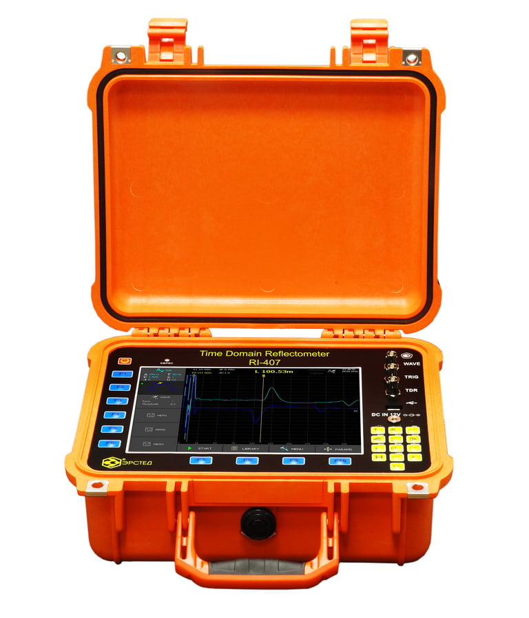
Cable Fault Locator TDR RI-407 – a high-precision digital reflectometer specifically designed to determine distances to all types of irregularities and faults in power cable lines: open circuit, short circuit, coupling, cable splice, parallel branch, wet cable.
The implementation of additional high-voltage methods makes it possible to locate high-resistance faults on power cables.
It can also be used on any other metal cable lines, communication cables, signaling and control cables, computer networks, television and radio frequency cable lines.
Overview
TDR RI-407 cable fault locator implements the following measurement methods:
- Time Domain Reflectometry (TDR)
- Arc Reflection Method(ARM or SIM )*
- Impulse Current Method (ICM)*
- DECAY travelling wave method*
* when used in complex with high-voltage pulse generators (HVPG), for example: ADG-200-2 “STINGRAY-M”
Time Domain Reflectometry (TDR)
the most accurate and safe mode – effective for diagnosing low-resistance faults (less than 1 kOhm) and short circuits, searching for cable line breaks, joints/splices, parallel branches, etc.
More about this method:
Time Domain Reflectometry (TDR). Theoretical basis.
Time Domain Reflectometry (TDR). Practical techniques.
The method allows you to perform the following works:
• cable length measurement;
• measurement of distances to impedance inhomogeneities or faults;
• measurement VoP (v/2) of the line at its known length;
• determination of the nature of cable fault.
The TDR method is based on the phenomenon of partial reflection of electromagnetic waves in places where the impedance of a line changes. When measuring by the TDR method, a short voltage probe pulse is sent to the line, which, partially reflected from the impedance inhomogeneities, returns back. The reflected pulses return to the TDR-device some time after the sending of the probe pulse. Knowing the signal velocity of propagation in the line and the delay time of the reflected signal, it is possible to calculate the distance to the impedance inhomogeneity (fault). Reflections from the probe pulse are observed on a range-scaled screen, and by their form can be determined the nature of inhomogeneity.
Inhomogeneities of the impedance are the result of a violation of the cable production technology, as well as a consequence of mechanical and electrical damage during the construction and operation of the cable. Inhomogeneity also occurs in the points where any devices are connected to the cable line (coupling, branch, cable splice/joint, Pupin coil, etc.), or in points of faults (open circuit, short circuit, wetting of the cable core, leakage to earth, leakage to an adjacent wire, broken pairs, etc.). The TDR method makes it possible to see multiple inhomogeneities, both discrete and distributed, depending on the ratio of their length and the minimum wavelength of the probe pulse spectrum.
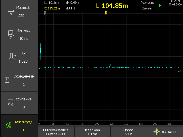
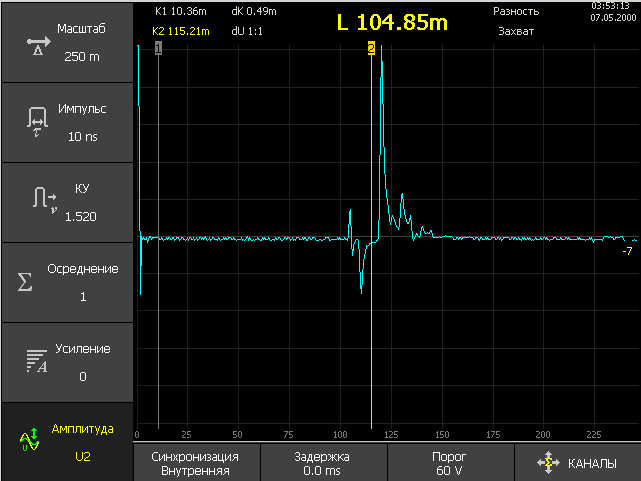
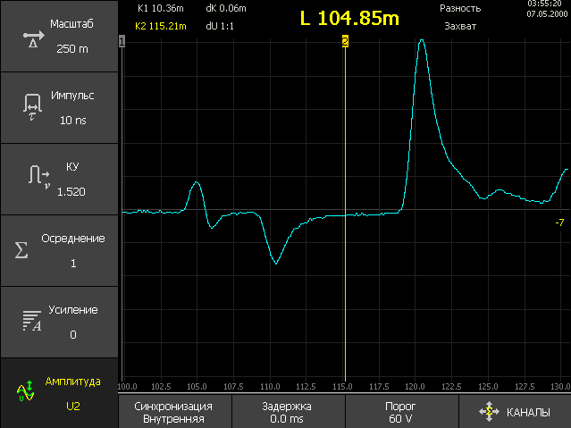
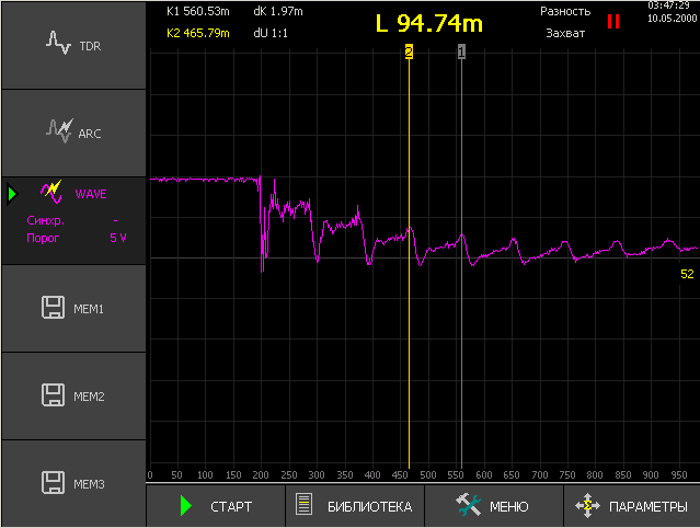
TDR RI-407 reflectogram examples:
Arc Reflection Method (ARM)
in combination with a High-Voltage Pulse Generator (HVPG), for example ADG-200-2 “STINGRAY-M”, allows to detect High-Resistance faults (> 1 kOhm) with the accuracy of the TDR method.
You can read more about this method at the link:
Arc Reflection Method (ARM) for high-resistance faults prelocation
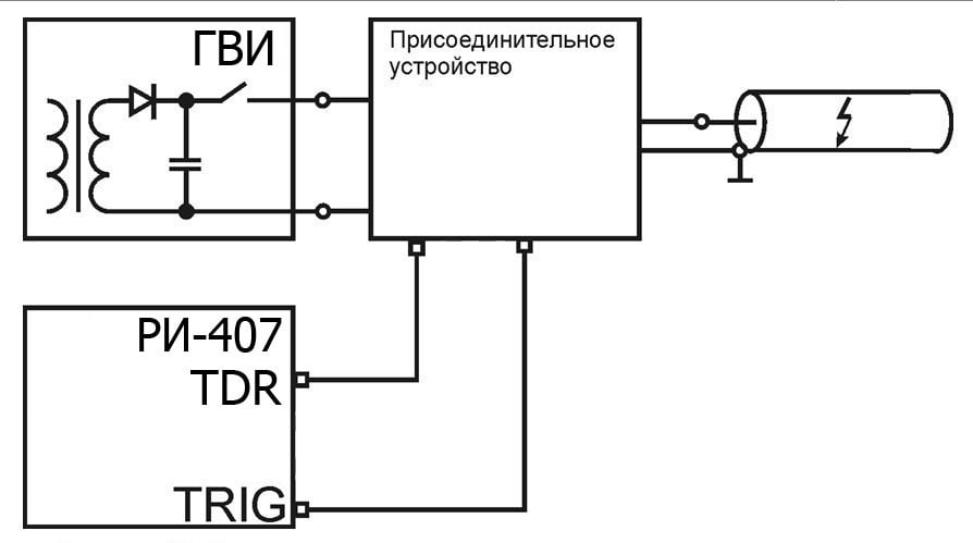
Localization of high-resistance faults at the site of a defect is usually difficult when using a low-voltage pulse measurement method. One of the ways to localize such defects on power cables is the Arc Reflection Method (ARM).
The essence of the ARM method is that a short-term electric arc is created (with the help of High-Voltage Pulse Generator ) at the place of cable damage. A burning electric arc has a low resistance, so it is well detected by an TDR.
The method does not require preliminary burning of the insulation and is especially effective when working on cables with a polyethylene sheath.
An example of reflectogram of a cable line obtained by a ARM method:

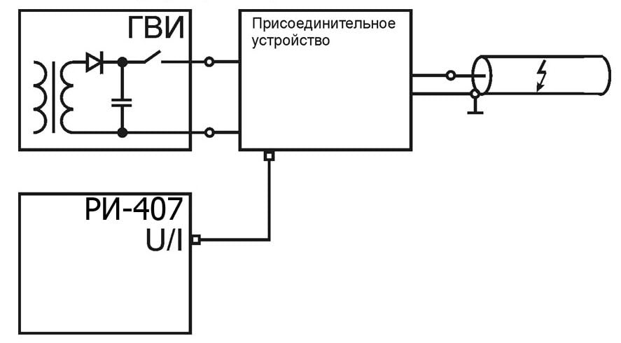
Impulse Current Method (ICM), DECAY travelling wave method
in combination with a High-Voltage Pulse Generator (HVPG), for example ADG-200-2 “STINGRAY-M”, it allows to determine the location of high-resistance defects in cases where the fault is distributed in nature and electrical breakdown occurs without ARC ignition (respectively, ARM is not applicable)
You can read more about this method at the link:
Impulse Current Method (ICM), DECAY travelling wave method for determining high resistance faults
Locating faults caused by a floating breakdown of insulation is usually difficult when using a low-voltage TDR measurement method. One of the ways to localize such defects on power cables is the oscillatory discharge method (ICM / Decay).
The method of oscillatory discharge (wave) is based on measuring the duration of the period of the oscillatory process that occurs during the breakdown of a charged cable.
To create an oscillatory process in the cable, with the help of HVPG, the voltage in the cable is smoothly raised to breakdown, but not higher than the value determined by the norms of preventive tests, or with the help of HVPG, the built-in high-voltage capacitor is charged and then discharged into the cable.
The reflectometer in this case acts as an oscilloscope that records the oscillatory process in the cable (using a current sensor – ICM method or voltage sensor – Decay method).
An insulation defect causes a breakdown at the place of damage, a and an oscillatory discharge occurs in the cable. Knowing the speed of propagation of the electromagnetic wave along the line and the period of the oscillatory process, it is possible to calculate the distance to the breakdown:
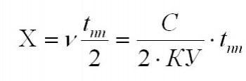
v – velocity of electromagnetic wave propagation in the cable , m / µs
tpp – time of the period of the oscillatory process, µs
s – speed of light equal to 299.8 m / µs
KU – the value of the shortening factor
TDR RI-407 cable fault locator technical specifications
Specifications | ||
| Measurement modes |
| |
| Display | color TFT 10” (800х600 px) | |
| Distance range (time delay) | from 0 to 256000 m (from 0 to 2560 us) | |
| Measurement subranges | 0 – 62.5 m (0 – 0.625 μs) 0 – 125 m (0 – 1.25 μs) 0 – 250 m (0 – 2.5 μs) 0 – 500 m (0 – 5 μs) 0 – 1000 m (0 – 10 μs) 0 – 2000 m (0 – 20 μs) 0 – 4000 m (0 – 40 μs) | 0 – 8000 m (0 – 80 μs) 0 – 16000 m (0 – 160 μs 0 – 32000 m (0 – 320 μs) 0 – 64000 m (0 – 640 μs) 0 – 128000 m (0 – 1280 μs) 0 – 256000 m (0 – 2560 μs) |
| Distance measurement error | 0.025% to 0.2% from subrange | |
| Effective sample rate | 800 MHz | |
| Output impedance | 75 Ohm | |
| Probing pulse duration | 10 ns to 100 μs | |
| Amplitude of the probing pulse (per open circuit) |
| |
| Receiving sensitivity | no worse than 10 mV | |
| Overlapped attenuation range | not less than 73 dB | |
| Shortening factor setting range | from 1.000 to 3.000, with a step of 0.001 | |
| Time delay adjustment range (pulse-arc method) | from 0 to 50 ms, in 0.2 ms increments | |
| Synchronization (pulse-arc method) |
| |
| Amplitude Sync (Wave Method) | -165 to +165 V, in 2 V steps | |
| Nonvolatile memory size for traces | at least 1000 traces | |
| PC interface | via external USB flash drive | |
| Continuous battery life | at least 6 hours | |
| Continuous operation time via network adapter | unlimited | |
| Dimensions | 152х339х295 mm | |
| Operating temperature range | -20 ° C to + 40 ° C | |
| Instrument weight with battery | no more than 4 kg | |
Features
- TDR RI-407 implements most effective and careful fault pre-location methods in the power cable : TDR, ARM, ICM, voltage Decay;
- Color 10.4″ TFT-display with a resolution of 800×600 pixels;
- Wide distance range – 1m … 256 km;
- Powerful probing pulse (up to U2 = 86 V on open circuit ) for operation on long cable lines or cable lines with high attenuation;
- Wide range of adjustable Pulse Width 10 ns …100 us;
- Extremely short dead-zone – 1m;
- Two-cursor measuring system;
- High measurement accuracy – up to 0.025%;
- Multiple Zoom feature – the possibility of a detailed view of any part of the reflectogram;
- Suppression of asynchronous interference – Averaging feature;
- Adjustable Digital Low-Pass Filter – for synchronous interference suppression;
- “Difference” feature – the mode of point-by-point subtraction of traces, which allows displaying only differences;
- “Capture” feature – the mode of detecting blinking faults – irregularities that are not constant in time;
- expandable built-in Сables Library;
- nonvolatile memory – at least 1000 detailed waveforms with the possibility of simultaneous display of up to 3 of them for comparison;
- the ability to adjust VoP and Сursors positions in the reflectograms already recorded in the memory with subsequent rewriting;
- “Screenshot” function that allows quickly save screenshot of the device in JPG file with date/time stamp; images are recorded to an external storage device simultaneously with the trace files and can be read by any graphic or text editor, which can be useful when drawing up reports;
- USB port for quick and convenient data exchange with a PC;
- expandable firmware functionality – easy and safe firmware update;
TDR RI-407 cable fault locator delivery contents:
Delivery contents | |
| Cable Fault Locator TDR RI-407 | 1 pc. |
| Power adapter DC 12V | 1 pc. |
| Connection cable 75 Ohm, 3 m, BNC.M – «crocodile» clips with working width 25.4 mm | 1 pc. |
| Connection cable 75 Ohm, 1 m, BNC.M-BNC.M | 2 pcs. |
| User Manual TDR RI-407 | 1 pc. |
| CD with software and documentation | 1 pc. |
| Accessory bag | 1 pc. |
Additional equipment |
| Arc Discharge Generator ADG-200-2 (10 kV, 200 J, 17kg) |
| Voltage protection unit UP-1 for operation on cables under voltage up to 380 V; |
| Extension cable 5 m, 75 Ohm, BNC.M-BNC.F |
| Connecting cable 1.5 m, 75 Ohm, BNC.M-crocodiles 25.4 mm |
| Connecting cable 0.1 m, 75 Ohm, & nbsp; BNC.M-crocodiles |
| Adapter BNC.M – terminals |
| USB-Flash drive |
IRView ver.5.0 (for TDR RI-407)
TDR RI-407 User Manual
Cable Fault Locator TDR RI-407. Specification.
Opereating cable fault locator TDR RI-407
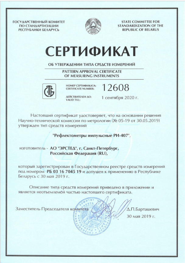
TDR RI-407 cable fault locator certificates:
Russian Federation : The device is certified by the State Standard of Russia and entered in the State Register under No. 61483-15. & nbsp; Certificate of type approval of measuring instruments RU.C.27.004A. # 59677.
Republic of Kazakhstan : The device is registered in the register of the State System for Ensuring the Uniformity of Measuring Instruments of the Republic of Kazakhstan under No. KZ.02.03.07316-2016 / 61483-15. Certificate No. 13246 on the type recognition of measuring instruments.
Republic of Belarus : The device is registered in the State Register of Measuring Instruments of the Republic of & nbsp; Belarus under No. RB 03 16 7045 19. Certificate No. 12608 on & nbsp; type approval of measuring instruments.