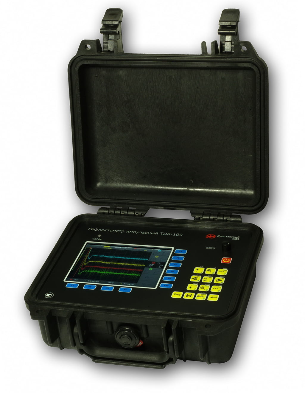
TDR-109 cable fault locator is a high-precision 3-channel time domain reflectometer designed to determine the distances to all types of faults in the power cable lines: open, short, sleeve, cable splice, parallel branches, wet cable, high-resistance faults, intermittent breakdown and etc.
Overview
TDR-109 cable fault locator implements the following measurement modes:
- Time Domain Reflectometry (TDR)
- Arc Reflection Method(ARM or SIM )*
- Impulse Current Method (ICM)*
- DECAY travelling wave method*
* when used in complex with high-voltage pulse generators (HVPG), for example: ADG-200-2 “STINGRAY-M”
Sphere of application:
The implementation of additional high-voltage methods makes it possible to locate high-resistance faults on power cables.
TDR TDR-109 is used for control when installing or operating the following types of cable lines:
- power cables;
- aerial cable lines;
- system cables communications;
- signal and control cables;
- computer networks;
- television and radio cable lines;
- to determine the length of the cable during its manufacture, storage and trade;
Implemented methods
TDR-109 cable fault locator implements the following measurement modes:
- Time Domain Reflectometry (TDR)
- Arc Reflection Method(ARM or SIM )*
- Impulse Current Method (ICM)*
- DECAY travelling wave method*
* when used in complex with high-voltage pulse generators (HVPG), for example: ADG-200-2 “STINGRAY-M”
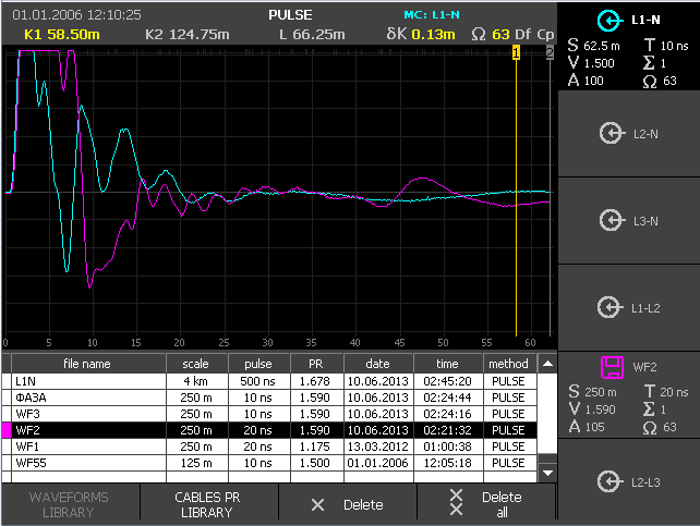
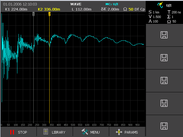
Time Domain Reflectometry (TDR)
the most accurate and safe mode – effective for diagnosing low-resistance faults (less than 1 kOhm) and short circuits, searching for cable line breaks, joints/splices, parallel branches, etc.
More about this method:
Time Domain Reflectometry (TDR). Theoretical basis.
Time Domain Reflectometry (TDR). Practical techniques.
The method allows you to perform the following works:
• cable length measurement;
• measurement of distances to impedance inhomogeneities or faults;
• measurement VoP (v/2) of the line at its known length;
• determination of the nature of cable fault.
The TDR method is based on the phenomenon of partial reflection of electromagnetic waves in places where the impedance of a line changes. When measuring by the TDR method, a short voltage probe pulse is sent to the line, which, partially reflected from the impedance inhomogeneities, returns back. The reflected pulses return to the TDR-device some time after the sending of the probe pulse. Knowing the signal velocity of propagation in the line and the delay time of the reflected signal, it is possible to calculate the distance to the impedance inhomogeneity (fault). Reflections from the probe pulse are observed on a range-scaled screen, and by their form can be determined the nature of inhomogeneity.
Inhomogeneities of the impedance are the result of a violation of the cable production technology, as well as a consequence of mechanical and electrical damage during the construction and operation of the cable. Inhomogeneity also occurs in the points where any devices are connected to the cable line (coupling, branch, cable splice/joint, Pupin coil, etc.), or in points of faults (open circuit, short circuit, wetting of the cable core, leakage to earth, leakage to an adjacent wire, broken pairs, etc.). The TDR method makes it possible to see multiple inhomogeneities, both discrete and distributed, depending on the ratio of their length and the minimum wavelength of the probe pulse spectrum.
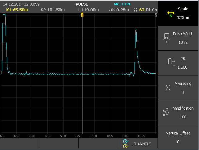
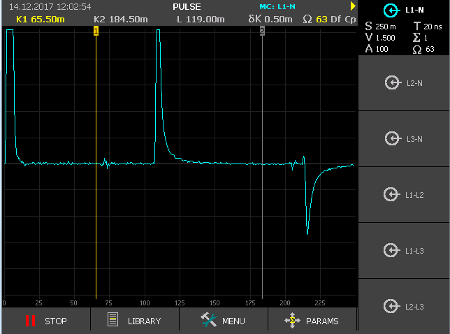
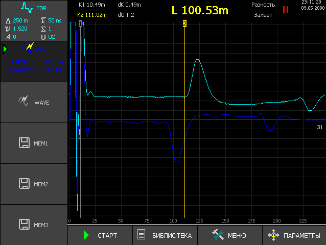
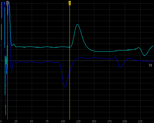
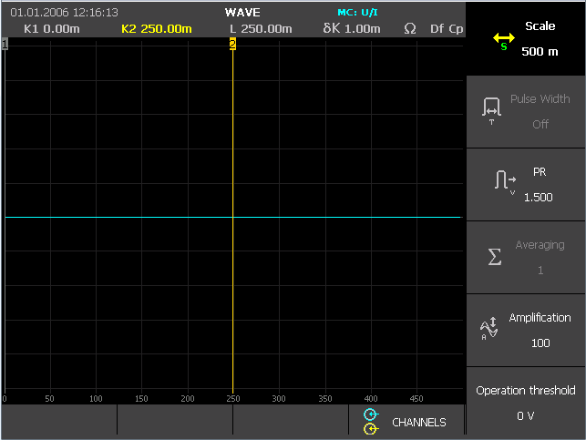
TDR-109 reflectogram examples:
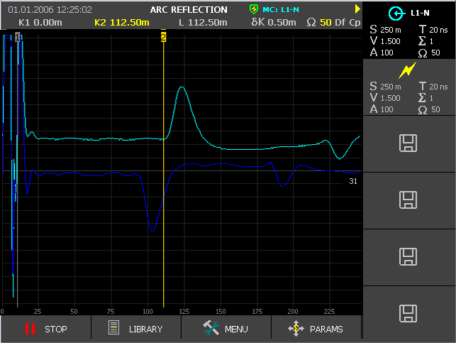
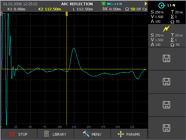
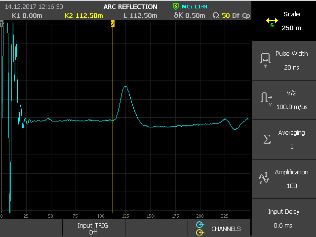
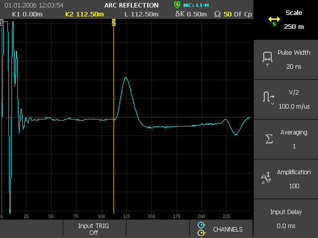
Arc Reflection Method (ARM)
in combination with a High-Voltage Pulse Generator (HVPG), for example ADG-200-2 “STINGRAY-M”, allows to detect High-Resistance faults (> 1 kOhm) with the accuracy of the TDR method.
You can read more about this method at the link:
Arc Reflection Method (ARM) for high-resistance faults prelocation
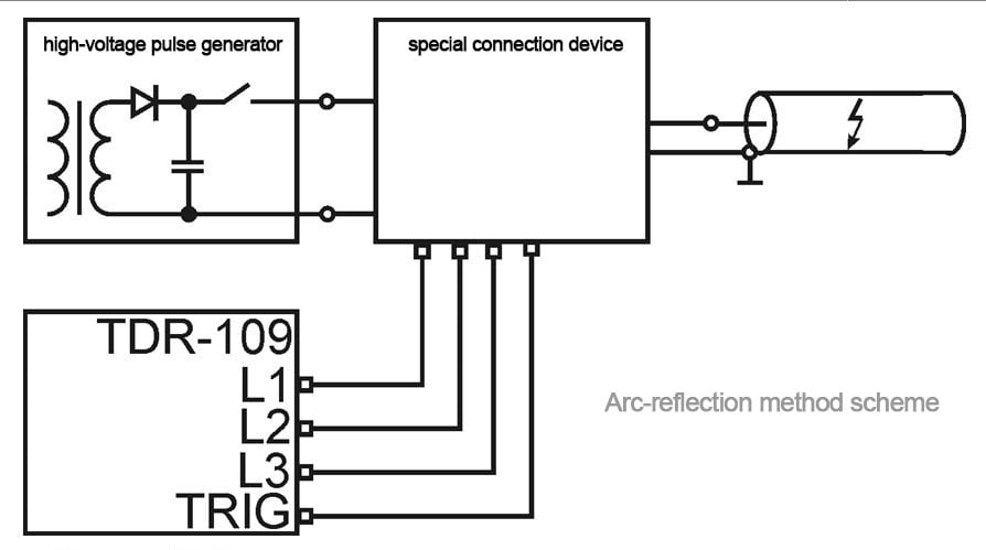
Localization of high-resistance faults at the site of a defect is usually difficult when using a low-voltage pulse measurement method. One of the ways to localize such defects on power cables is the Arc Reflection Method (ARM).
The essence of the ARM method is that a short-term electric arc is created (with the help of High-Voltage Pulse Generator ) at the place of cable damage. A burning electric arc has a low resistance, so it is well detected by an TDR.
The method does not require preliminary burning of the insulation and is especially effective when working on cables with a polyethylene sheath.
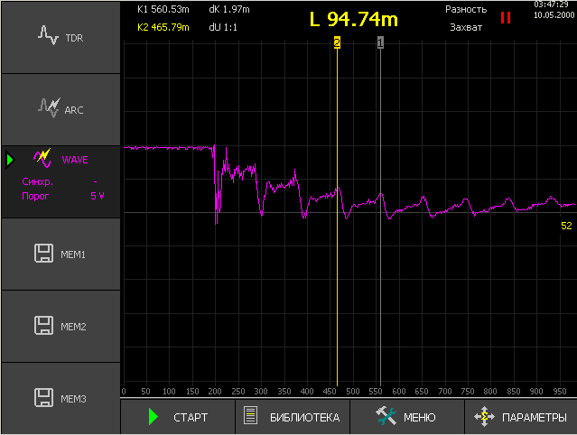
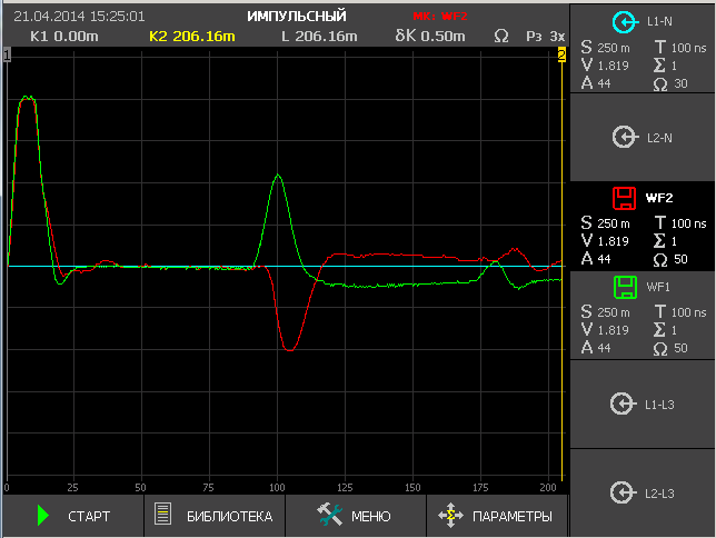
An example of reflectogram of a cable line obtained by a ARM method:

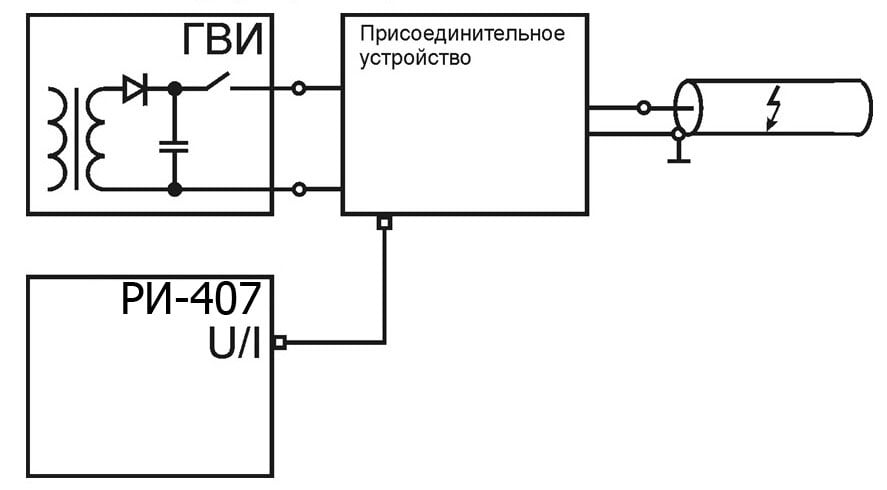
Impulse Current Method (ICM), DECAY travelling wave method
in combination with a High-Voltage Pulse Generator (HVPG), for example ADG-200-2 “STINGRAY-M”, it allows to determine the location of high-resistance defects in cases where the fault is distributed in nature and electrical breakdown occurs without ARC ignition (respectively, ARM is not applicable)
You can read more about this method at the link:
Impulse Current Method (ICM), DECAY travelling wave method for determining high resistance faults
Locating faults caused by a floating breakdown of insulation is usually difficult when using a low-voltage TDR measurement method. One of the ways to localize such defects on power cables is the oscillatory discharge method (ICM / Decay).
The method of oscillatory discharge (wave) is based on measuring the duration of the period of the oscillatory process that occurs during the breakdown of a charged cable.
To create an oscillatory process in the cable, with the help of HVPG, the voltage in the cable is smoothly raised to breakdown, but not higher than the value determined by the norms of preventive tests, or with the help of HVPG, the built-in high-voltage capacitor is charged and then discharged into the cable.
The reflectometer in this case acts as an oscilloscope that records the oscillatory process in the cable (using a current sensor – ICM method or voltage sensor – Decay method).
An insulation defect causes a breakdown at the place of damage, a and an oscillatory discharge occurs in the cable. Knowing the speed of propagation of the electromagnetic wave along the line and the period of the oscillatory process, it is possible to calculate the distance to the breakdown:
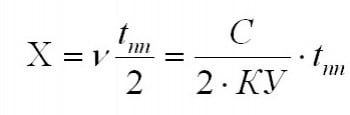
v – velocity of electromagnetic wave propagation in the cable , m / µs
tpp – time of the period of the oscillatory process, µs
s – speed of light equal to 299.8 m / µs
KU – the value of the shortening factor
Features:
- the possibility of applying the most modern methods of diagnosis and cable fault prelocation: TDR method, Arc-Reflection Method (ARM), the voltage wave(Decay), the method of the current wave(ICM);
- 3 line inputs to connect to the three phase cables;
- display waveforms on a color 5.7 ” TFT-LCD with a resolution of 640×480 pixels;
- the ability to display all measurement channels in all combinations (6 waveforms);
- non-volatile memory – at least 1000 waveforms, up to six of them for comparison;
- subtraction mode to show only waveform differences;
- maximum range – 128 km;
- the possibility of sensing with an increased pulse amplitude (U2 = 86 V on open circuit ) to work on cables with high attenuation;
- real time measuring;
- two cursors measuring system;
- possibility of a detailed review of any portion of the reflectogram – the function of multiple zoom;
- asynchronous noise suppression;
- intermittent fault mode detection – the function “Capture”;
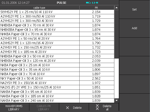
- built-in velocity factor table up to 300 values;
- External USB Flash drive to archive waveforms library and VOP library, as well as restore libraries to the device memory from USB flash;
- splash proof and hermetically closing body with high mechanical strength (protection class IP67);
TDR-109 cable fault locator Specifications
| Measurement Modes |
|
| Display | Color TFT 5.7″ (640×480 pixels) |
| Range measuring distance (delay time) | from 0 to 128000 m (0 to 1280 μs) |
| Sub-bands of distance (time delay) | 0 – 62.5 m (0 – 0,625 μs), 0 – 125 m (0 – 1.25 μs), 0 – 250 m (0 – 2.5 μs), 0 – 500 m (0 -5 μs); 0 – 1000 m (0 – 10 μs), 0 – 2000 m (0 – 20 μs), 0 – 4000 m (0 – 40 μs), 0 – 8000 m (0 – 80 μs) 0 – 16000 m (0 – 160 μs), 0 – 32000 m (0 – 320 μs) 0 – 64000 m (0 – 640 μs) 0 – 128,000 m (0 – 1280 μs) |
| Distance instrumental error | from 0.01% to 0.2% of subband (from 12.5 cm to 8 m at VOP = 60%) |
| The effective sampling rate | 800 MHz |
| Range concerted resistance | from 20 Ω to 600 Ω |
| Probe pulse duration | from 10 ns to 100 μs |
| The amplitude of the probe pulse (at open circuit) |
|
| The sensitivity of the receiving path | better than 1 mV |
| The dynamic range | not less 80 dB |
| The setting range of the velocity factor | from 1.000 to 3.000 (step 0.001) |
| Time delay adjustment range (Arc-Reflection method) | from 0 to 50 ms (step 0.2 ms) |
| Synchronization (Arc-Reflection method) |
|
| Amplitude synchronization (wave method) | -60 to +60 V, step 2V |
| Continuous battery operating time | at least 6 hours |
| Time of continuous operating time through the charger | unlimited |
| Dimensions | 70x246x124 mm |
| Operating temperature range | from -20 °C to +40 °C |
| Weight with a battery | not more than 2.5 kg |
TDR-109 cable fault locator Delivery Contents
| Quantity | |
| Cable Fault Locator TDR-109 | 1 item |
| AC Adapter 12 V | 1 item |
| Connecting cable 75 Ohm, BNC.M – «Alligator clip» | 1 item |
| Connecting cable 75 Ohm, 1 m, BNC.M-BNC.M | 5 items |
| User Manual | 1 item |
| CD-ROM with software | 1 item |
| Accessories bag | 1 item |
Additional equipment
| Arc Discharge Generator ADG-200-2 (10 kV, 200 J, 17kg) |
| Voltage protection unit UP-1 for operation on cables under voltage up to 380 V; |
| Extension cable 5 m, 75 Ohm, BNC.M-BNC.F |
| Connecting cable 1.5 m, 75 Ohm, BNC.M-crocodiles 25.4 mm |
| Connecting cable 0.1 m, 75 Ohm, & nbsp; BNC.M-crocodiles |
| Adapter BNC.M – terminals |
| USB-Flash drive |
Cable Fault Locator TDR-109. Specification
TDRView ver.5.0. eng (for TDR-109)
TDR-109 User Manual

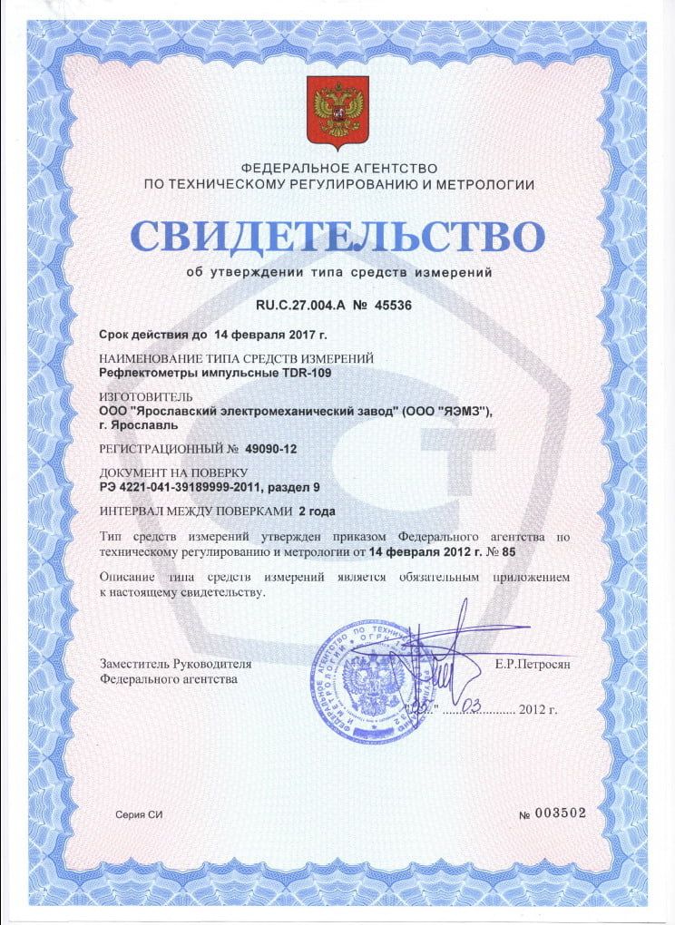
TDR-109 cable fault locator Certificates
The device is certified by the State Standard of Russia and entered in the State Register under No. 49090-12. Certificate of type approval of measuring instruments RU.C.27.004.A No. 45536